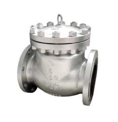
Three-way control valve
The three-way control valve is a type of multi-port control valve. According to the action mode of the fluid, the three-way control valve can be divided into two types: converging valve and diverging valve. The confluence valve has two populations and flows out from one outlet after confluence. The diverter valve has a fluid population, which is divided into two streams and flows out from two outlets. Shown in the figure is the structure diagram of the split three-way regulating valve. The structure of the confluence three-way control valve is similar to that of the split three-way control valve. The characteristics of the three-way control valve are as follows.
1. The three-way regulating valve has two valve cores and valve seats, and its structure is similar to that of a double seat valve. However, in a three-way control valve, when the flow area between one valve core and the valve seat increases, the flow area between the other valve core and the valve seat decreases. In a double seat valve, the flow area between the two valve cores and the valve seat increases or decreases at the same time.
2. The air opening and closing of the three-way regulating valve can only be achieved by selecting the positive and negative effects of the actuator. The change of the air opening and closing of the double seat valve can be realized by directly installing the valve body or valve core and the valve seat in reverse.
3. When the three-way regulating valve is used in a control system that requires fluid to be proportioned, since it replaces an air-open control valve and an air-close control valve, it can reduce costs and reduce installation space.
4. The three-way regulating valve is also used in places where the bypass is controlled. For example, one fluid passes through the heat exchanger to exchange heat, and the other fluid does not exchange heat. When the three-way regulating valve is installed in front of the heat exchanger, the split three-way regulating valve is adopted; when the three-way regulating valve is installed behind the heat exchanger, the converging three-way regulating valve is adopted. Since the fluid flowing in the three-way regulating valve installed in front of the heat exchanger has the same temperature, the leakage is small; the fluid flowing in the three-way regulating valve installed behind the heat exchanger has different temperatures, The expansion degree of the valve core and the valve seat is different, therefore, the leakage is larger. Generally, the temperature difference between the two fluids should not exceed 150C.
5. The leakage of the three-way control valve has a great relationship with the structure, and the leakage level can be from II to IV.
The three-way control valve shown in the figure adopts a cage structure with a balance hole and is guided by the cage. Therefore, the unbalanced force can be greatly reduced. The early three-way control valve used a cylindrical thin-walled window and was guided by the side of the spool. Although it could reduce the unbalanced force, there was still a large unbalanced force when a stream of fluid was close to closing (flow direction). Moreover, as the valve opening changes, the unbalanced force changes. The cage structure with balance holes as shown in the figure can eliminate the unbalanced force and has a damping effect, which is beneficial to the stable operation of the control valve. The three-way control valve guided by the valve stem has a relatively large balance force, and the required driving thrust is related to the fluid outlet, the population pressure, the friction force and the pressing force.
Due to the large leakage of the three-way control valve, in applications where a small leakage is required, two control valves (and a three-way connector) can be used to split or merge fluids, or to control the proportion of fluids.
Three-way valve and sleeve valve
Sleeve control valve
Sleeve control valve as shown in the figure, also known as cage valve. The structure of the valve body is similar to that of a straight-through control valve, and it is also composed of a valve body, a valve core, a guide sleeve, an upper valve cover, an upper cover plate, a valve stem, and packing. Its structural feature is the use of valve core and valve cage (sleeve) for internal parts. The sleeve regulating valve is guided by the inner surface of the cage, and the cage is used to throttle the opening to meet the required flow characteristics.
The features of the sleeve control valve are as follows.
1. Convenient installation and maintenance: The valve seat is tightly pressed on the valve body through the valve cover, and no threaded connection is used, which is convenient for installation and maintenance.
2. Convenient to change the flow characteristics: The flow out of the sleeve in the sleeve regulating valve is called the outward flow from the center, and vice versa, the flow from the outside to the center. Shown in the figure is the structure diagram of the straight-through sleeve regulating valve that flows from the outside to the center. However, it is usually used to flow from the lower part of the sleeve and flow out through the opening of the valve cage, which is opposite to the flow direction in the figure. 3, 4 or .6 throttle openings are symmetrically distributed on the sleeve. The shape of the throttle opening is related to the required flow characteristics. Therefore, the sleeve (the shape of the throttle opening) can be easily replaced to change the control The flow characteristics of the valve.
3. Noise reduction and cavitation reduction: In order to reduce the noise of the control valve, there is a type of sleeve control valve with noise reduction valve trim. Its sleeve and valve core have multiple small holes, which use small holes to increase resistance, convert the speed head into kinetic energy, and reduce noise. Generally, this kind of sleeve regulating valve can reduce noise by more than 10dB, so it is widely used in noise reduction occasions. In order to reduce the control valve noise, a multi-stage pressure reduction method can also be used. The total pressure drop at both ends of this type of noise reduction control valve is distributed to all levels, so that each level will not cause flashing and cavitation of the fluid, thereby reducing the noise of the control valve, and weakening and preventing flashing and cavitation Scour and wear caused by. The bottom of the sleeve control valve spool is flat. If cavitation occurs, the impact generated by the bubble burst will not act on the spool, but will be absorbed by the medium itself. Therefore, the sleeve control valve has little cavitation impact and has a long service life.
4. Leakage is larger than single-seat valve: Because there is a graphite piston ring seal between the sleeve and the valve core, after long-term operation, the wear of the seal ring makes the leakage of the sleeve control valve larger than that of the single-seat valve.
5. High interchangeability and versatility: Replace different sleeves to obtain different flow coefficients and different flow characteristics.
6. Reduce the impact of unbalanced force: Generally, there are two types of sleeve control valves, one is a balanced valve, and the other is an unbalanced valve. The valve core of the balance valve is provided with a balance hole, which greatly reduces the unbalanced force on the valve core. At the same time, it has a damping effect, which is beneficial to the stable operation of the control valve. Therefore, this type of control valve is often used in applications where the pressure difference is large and low noise is required.
7. Since the valve core can be disassembled from the lower part of the anti-body sleeve regulating valve, it is especially suitable for occasions where the internal parts of the valve need frequent inspection and maintenance.

